
INSTALLATION GUIDE
Flex Systems Junction Box Installation Guide
This guide covers the installation of Flex Systems junction boxes. While the number of circuits varies between models, the enclosure, cable glands and lever-terminal installation method are consistent across the range.
Before You Begin
Plan the mounting position and cable routing before beginning the installation. The junction box should remain accessible for future inspection and maintenance.
- Disconnect the trailer or vehicle from power.
- Confirm the junction box is suitable for the intended application.
- Inspect the enclosure, gasket, glands and terminals before installation.
- Identify each trailer circuit before disconnecting existing wiring.
- Plan the mounting location and cable entry direction.
Recommended Tools
Wire Strippers
For preparing conductors without damaging the copper strands.
Side Cutters
For trimming cable and conductors cleanly.
Screwdriver
For fitting and removing the junction-box lid.
Drill and Fasteners
For securely mounting the enclosure to the trailer.
Multimeter or Test Light
For identifying circuits and completing final electrical testing.
STEP ONE
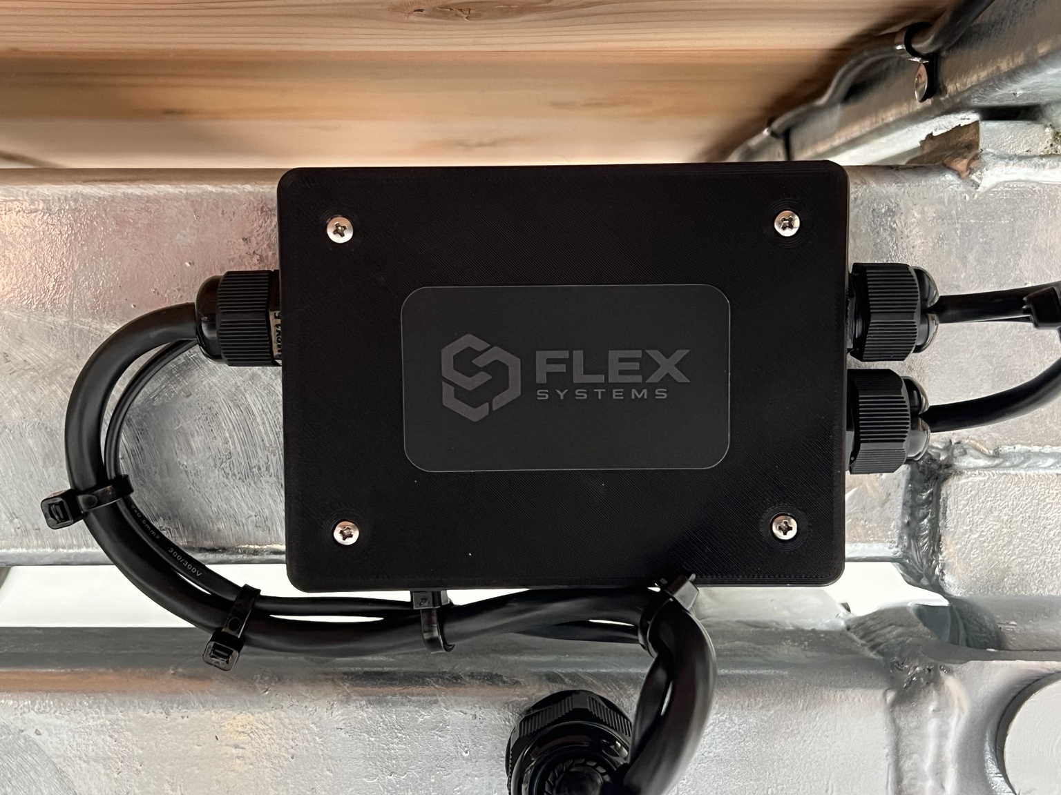
Choose the Mounting Location
Mount the junction box to a solid, stable surface using fasteners appropriate for the trailer construction.
Choose a position that:
- Allows the cables to enter without tight bends or strain.
- Provides access for future inspection and servicing.
- Protects the enclosure from direct impact and road debris where practical.
- Does not allow the junction box to sit in pooled water.
- Allows the lid to be removed without disturbing surrounding equipment.
STEP TWO
Prepare the Cable Entries
Feed each cable through its cable gland before terminating the individual conductors.
- Loosen the gland sufficiently to allow the cable to pass through.
- Feed enough cable into the enclosure to reach the terminals without tension.
- Avoid sharp bends immediately beside the cable gland.
- Do not fully tighten the glands until the wiring is complete.
STEP THREE
Prepare the Conductors
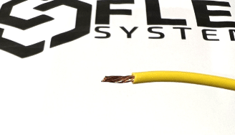
Strip approximately 10–12 mm of insulation from each conductor. The exposed conductor should be long enough to enter the terminal fully without leaving bare copper visible outside the terminal body.
- Use a suitable wire stripper.
- Do not cut or nick the copper strands.
- Remove any damaged section and prepare the conductor again.
- Keep the conductor strands together before inserting them.
STEP FOUR
Use the Lever Terminals
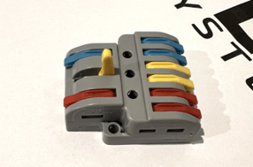
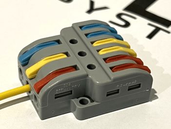
Flex Systems junction boxes use vibration-resistant lever terminals to provide a secure and service-friendly connection method.
Lift the Lever
Lift the orange lever fully to open the terminal before inserting the conductor.
Insert the Conductor
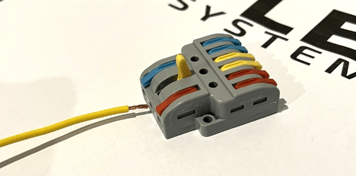
Insert the stripped conductor fully into the terminal opening. Ensure the copper reaches the internal connection point.
Close the Lever
Push the lever completely down to secure the conductor.
Complete a Tug Test
Lightly pull the conductor to confirm it is securely retained. If it moves, reopen the lever and repeat the connection.
STEP FIVE
Connect the Trailer Circuits
Connect each conductor to the correctly labelled terminal inside the junction box. The available circuits depend on the junction-box model.
Identify and verify each circuit before making the final connection. Do not rely only on cable colour, particularly when working on existing or previously modified trailer wiring.
- Follow the terminal labels inside the junction box.
- Check conductor identification before connection.
- Confirm polarity where applicable.
- Keep conductors neatly routed inside the enclosure.
- Avoid placing conductors where they may be trapped by the lid.
STEP SIX
Secure the Cable Glands
Once the conductors are connected and correctly positioned, tighten each cable gland until it grips the outer cable sheath securely.
- Ensure the gland seals around the outer cable sheath.
- Do not attempt to seal around individual conductors.
- Confirm the cable cannot move freely through the gland.
- Do not apply excessive force or over-tighten the gland.
STEP SEVEN
Fit the Lid
Before fitting the lid:
- Confirm every conductor has completed a light tug test.
- Check that no bare copper is visible outside the terminals.
- Ensure no wires are trapped between the enclosure and lid.
- Check that the gasket is clean, undamaged and correctly seated.
- Confirm the cable glands are tightened correctly.
Position the lid carefully and tighten the lid screws evenly. The screws should be secure without being over-tightened.
STEP EIGHT
Complete the Final Test
Reconnect power only after the installation has been checked. Test every trailer function before towing or placing the trailer back into service.
All conductors are connected to the correct labelled terminals.
Every conductor is securely retained.
The cable glands grip the cable sheaths correctly.
The gasket and lid are seated correctly.
All trailer lighting and electrical functions operate correctly.
Inspection and Maintenance
Inspect the junction box periodically and whenever the trailer wiring is serviced.
- Check that the enclosure remains securely mounted.
- Inspect cables and cable glands for damage or movement.
- Check the lid, gasket and fasteners.
- Look for evidence of water ingress or physical damage.
- Confirm the internal conductors remain secure and organised.
Replace damaged components before continuing to use the trailer.
Water Exposure
Flex Systems junction boxes are designed for normal outdoor trailer use, including exposure to rain, road spray and general weather conditions.
They are not designed for water submersion or installation in a location where prolonged immersion is expected.
Need Assistance?
If you have questions about your Flex Systems junction box or are unsure which product suits your trailer, contact Flex Systems before continuing with the installation.
Contact Flex Systems